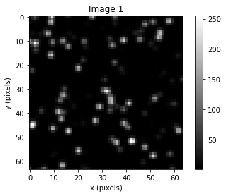
Here, you select a specific variable to change across several values, while holding all other values constant, to identify the impact of individual variables on the resulting correlation plane. For example, to identify the impact of different particle image diameters, select “Particle Image Diameter”. When selected, a series of pre-determined synthetic interrogation region images and relevant discussion allow you to observe and read about the influence of particle diameter on correlation plane characteristics and the likely vector output accuracy. Further, selecting the “Run Simulation” button (warning: takes some time) will generate new synthetic images across particle image diameters of 0.5-3 pixels, allowing you to observe the influence of particle diameter on correlation plane peak size for more images. While these results are qualitative and the errors anecdotal, reading about how the correlation plane is calculated (Learn PIV>How PIV Works) concurrent with these observations should help you understand why certain parameters are better than others (e.g., when particle images are too small, there isn’t enough signal, and the correlation peak is likely to be too weak!).
Particle Image Diameter
Density
Theta
Noise Mean
Region Size
S and R (X, Y Displacement)
Shear X and Y
Your images are being generated, please do not leave the page until generation is complete.
0 out of 15 images generated...
3 out of 15 images generated...
6 out of 15 images generated...
9 out of 15 images generated...
12 out of 15 images generated...
Particle Image Diameter
Particle Image Diameter: 0.5 |
Particle Image Diameter: 1 |
Particle Image Diameter: 1.5 |
Particle Image Diameter: 2 |
Particle Image Diameter: 3 |
|
|
|
|
|
|

|

|

|

|

|
| U error: -2.500, V error: -5.600 |
U error: 0.038, V error: 0.167 |
U error: -0.014, V error: 0.117 |
U error: 0.019, V error: 0.078 |
U error: 0.051, V error: -0.017 |
|
The particle image diameter variable manually determines the size of the particle images in the interrogation regions (see: Particle Image Diameter Page). Traditionally, the particle image diameter should be larger than 2 pixels. This requirement is due to the fact that small particle diameters remove the ability for sub-pixel estimation methods to work effectively, and this results in integer valued displacements. This effect is known as peak locking and PIV experimenters should avoid these effects whenever possible by maintaining particle image diameters at or above 2 pixels. Further, smaller particle images provide insufficient signal (i.e., information). Consider the images for the Diameter of 0.5 pixels. Here, the particles are only imaged as a single pixel. This small amount of signal only allows the correlation plane to show a small-value, narrow, peak at the true displacement. However, larger particle images provide more signal, making the correlation stronger. This increase is demonstrated through the increase in the maximum value of C(r,s) in the example images. At diameter=0.5, the correlation peak is less than 2,000. This correlation value increases as the particle image diameter increases, and at Diameter = 3 pixels the correlation peak is at 800,000!
|
|
|
|
|
|
|
Density
Density: 0.01 |
Density: 0.02 |
Density: 0.04 |
Density: 0.10 |
Density: 0.50 |
|
|
|
|
|
|

|

|

|

|

|
| U error: 3.578, V error: -5.680 |
U error: -0.270, V error: -0.282 |
U error: 0.039, V error: 0.009 |
U error: 0.018, V error: 0.053 |
U error: 0.057, V error: 0.106 |
|
The density variable manually determines how many particles are in each image (see: Particle Density Page). Specifically, the units for density are particles/pixel. The density of particles in an image determines how many particles are likely to be correlated for a given interrogation region size. With too few particles, the number of particles consistent in the first and second image is likely to be too low and can result in erroneous vectors (see density=0.01). Increasing the number of particles in the flow field provides more “signal” and increases the strength of the correlation. Notice how the true correlation peak becomes more distinct and the maximum value of the correlation increases as the density increases. At the upper limit of this, however, the correlation peak becomes less distinct from the background when there are too many particles. Notice how this occurs at density = 0.5. PIV experimenters should balance the number of particles to maintain a good signal while allowing each particle to provide a distinct image.
|
|
|
|
|
|
|
|
Theta
Theta: 0$^{\circ}$ |
Theta: 5$^{\circ}$ |
Theta: 10$^{\circ}$ |
Theta: 15$^{\circ}$ |
Theta: 20$^{\circ}$ |
|
|
|
|
|
|

|

|

|

|

|
| U error: 0.006, V error: 0.021 |
U error: -0.083, V error: -0.017 |
U error: -0.088, V error: 0.223 |
U error: -1.593, V error: 5.259 |
U error: -3.530, V error: -4.279 |
|
The theta variable controls the motion of particles into and out of the image plane (see: Theta Page). In the images above, at theta of 0, the particles only move in the direction of the image plane. As a result, you can track each particle with your eyes from the first to second image (assuming the particles don’t leave the edge of the image). However, if the flow and laser plane are at an angle (theta), the particles move in/out of the brightness of the laser sheet. For increasing values of theta, visually tracking each particle image shows the particles lose/gain intensity between each image. At a theta value of 20 degrees, few particles are consistent from the first and second image. If particles enter/leave the image plane between images, their contribution to the correlation is lost and these particles act as noise. This result is shown in the correlation plane(s), where an increase in theta reduces the distinctness of the true correlation peak and increases the output error(s). PIV experimenters should avoid out of plane motion as much as possible by aligning the laser plane with the flow direction and using planar PIV (the methods discussed here) for approximately two-dimensional flows.
|
|
|
|
|
|
|
|
Noise Mean
Noise Mean: 0 |
Noise Mean: 0.5 |
Noise Mean: 1 |
Noise Mean: 2 |
Noise Mean: 3 |
|
|
|
|
|
|

|

|

|

|

|
| U error: 0.006, V error: 0.021 |
U error: -0.098, V error: 0.088 |
U error: 0.132, V error: 0.029 |
U error: 0.212, V error: -0.023 |
U error: -0.352, V error: 0.295 |
|
The noise mean variable directly determines the amount of noise added to each image pair (see: Noise Mean Page). Increasing the noise mean increases the amount of random intensity values added to each image pixel. Noise in the images leads to noise in the correlation plane, making the true correlation peak less distinct. Consider the noise mean of 0, only particles are contributing to the image pixel intensities, and the true correlation peak is easy to distinguish from the rest of the correlation plane. However, increasing noise reduces this distinctness. At a noise mean of 3, the particles are hard to distinguish from the noise, and as a result, the correlation peak is similar in magnitude and distinctness to the random incorrect peaks in the correlation plane. PIV experimenters should reduce noise as much as possible. While random noise (as added here) is usually low, objects in the background or foreground are common sources of PIV noise. Similarly, when conducting PIV around an object, the object is often illuminated. These sources all introduce noise, and experimenters should reduce these contributors to PIV error whenever possible.
|
|
|
|
|
|
|
|
Region Size
Region Size: 16 |
Region Size: 32 |
Region Size: 64 |
Region Size: 128 |
|
|
|
|
|
|
|

|

|

|

|
|
| U error: 15.120, V error: 5.091 |
U error: -0.073, V error: 0.167 |
U error: 0.038, V error: 0.034 |
U error: 0.014, V error: 0.021 |
|
|
The region size variable controls the size of the images generated then correlated (see Region Size Page) balance. Choosing an appropriate interrogation region or “window” size in PIV involves trade-offs. A larger window increases the number of particles per correlation and can increase the likelihood of finding a valid correlation. Increasing the window size, however, also decreases the spatial resolution of the displacement of the particles in each interrogation region. Further, if the particle displacements vary within a given region, the output vector may be less representative of the particles near the center of the region (where the output vector is returned/placed). The demonstration images have a fixed displacement of 10 and 5 pixels in the s and r directions respectively. For the region size of 16, the region size is too small and almost all the particles are “lost” between the first and second images resulting in an invalid correlation. For the region size of 32, sufficient particles are retained between the first and second image and the true correlation peak is in the correlation plane. As the region size increases beyond 32, however, the displacement is small compared to the correlation plane. This is an indication that the output resolution is suffering at the expense of large interrogation regions. PIV experimenters should try to make the interrogation regions as small as possible to obtain valid correlations while maximizing resolution. Further, multi-pass methods (see Multi-pass Page) balance these issues well.
|
|
|
|
|
|
|
S and R (X, Y Displacement)
|
Shear X and Y
|